|
|
Building an APRS Trackers
by Clint Anderson AE5CA and John Chamberlain AC5JC
On the previous page we described the history and use of our custom built trackers. Here we will give more details about the creation and design of the package, as pioneered by Larry Bush W5NCD.
Choice of Hardware
- Firmware: The TinyTrak3+ (TT3+) from Byoniocs.com uses a tiny circuit board (or a flexible surface mount version may also be available) to
- collect real-time GPS data,
- format the data for short APRS packets, and
- transmit the APRS packets at programmable intervals using a PTT connection with a connected radio.
- Packaging: The TT3+ circuit board can fit into a tiny matchbox sized container, or as Larry Bush discovered, into the battery case of a small handheld radio.
- Radio: The Icom V8 or Icom V80 radios are ideally suited for this application:
- Economically priced (~$100 each),
- A removable battery holder (not a "battery pack," but a case that holds AA batteries),
- Microphone jack with non-powered PTT control, and earphone jack,
- Auto-power up mode that turns On the radio when power is supplied,
- Delivers a 5 watt output,
- Several other desirable configuration options (squelch, key lock, etc.)
- GPS receiver: a serial output is required to deliver the data stream required by the TT3+ circuit. The GPS receiver should be externally powered though the same connection (cable). This generally dictates a "puck" type of receiver unit, not a handheld, hiking type.
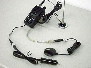
- Antenna: For automotive applications, an external mag-mount style antenna with the correct connector for the radio and sufficient cable length for rooftop mount is recommended for adequate range. For hiking applications, the stock rubber-duck or short whip may suffice.
- Power: The modifications below are designed for a 9 to 15 VDC supply able to deliver about 7 watts of intermittent transmit power. Clearly, for automotive applications, a 1 A, 12-13 VDC source will suffice. For long-term installations, connect to a power line that will disconnect when the vehicle is turned OFF. For hiking applications, you can deliver power from a 9V or 12V battery back.
Constructing the Tracker in the Battery Holder of an Icom V8 or V80 radio
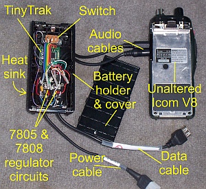
- Using a mill, first remove the "guts" (plastic ridges, conductors, springs, etc.) designed to hold the AA batteries. We'll use this space to contain two printed circuit cards and wiring. One of the cards will deliver 8 VDC to the radio in lieu of the batteries. At this time you can also mill out a tiny slot to support a slide switch (see below).
- We will install two circuit boards into the battery holder. The first circuit board is for power regulation and supply: using 7805 and 7808 regulator chips, a board custom designed by W5NCD. These two chips take 12 VDC supplied from the vehicle's cigarette lighter plug and convert it to
- 5 VDC to power the TT3+ circuit, and
- 8 VDC to power the Icom radio. The output of the 7808 is connected to the terminals on the battery holder that will make contact with the main body of the radio when snapped into place.
The 7805 included on the Tiny Track PC board is not used. (It would likely get too hot when supplied with 12V.)
- Instead of using the DB-9 input/output connectors on the Tiny Track board, we solder several pigtails (cables) directly to the TT3+ circuit board and power-regulation boards and exit the battery holder through several small added holes. To save space, we simply remove (unsolder) the DB9 connectors. As shown in the photo above, four "pigtails" emerge from the case and connect to
- Audio cable to the radio earphone jack (via 2.5 mm audio plug),
- Audio/PTT cable to the radio microphone jack (via 3.5 mm stereo audio plug),
- Data cable to the satellite GPS receiver (via 6-pin DIN or DB9)*, and
- Power cable to 12 VDC power source (via cigarette lighter or dual-pin plug).
(Image above shows a different connector, not a DIN or DB9.)
- To dissipate the heat generated by our two voltage regulators, we mount a heat sink to the battery holder, and a thermal connection between the chips and the heat sink.
- A DPST slide-switch is also mounted to the battery holder case to permit choosing between the two possible TT3+ configurations (as described on the previous page).
Connecting the TinyTrak Package to the Outside World
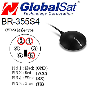
- GPS Receiver and Connections. The TT3+ needs GPS data. You can use any GPS "puck" that provides a serial (RS-232) NMEA data stream. (NOTE: Receivers with USB connectors are not serial.) Hint: Older GPS receivers will work, but perform poorly with window tinting, trees, tall buildings, etc. We have had good success with the reasonably priced GlobalSat BR-355-S4 (available from amazon.com) with a 6 pin mini-DIN connector for power In (pins 1 and 2) and data transfer (pin 5). If your older GPS receiver has a DB9 connector, you can configure everything to use the DB9 instead of the mini-DIN connector.
- Data cable. The TT3+ gets it data through this pigtail cable: either lat-lon data from the GPS receiver or configuration data from a computer. We've tried various connectors, and settled on the DIN connector as being most reliable and an obvious choice for connecting the GPS receiver. Starting with a PS-2 extender mini-DIN cable (male and female connectors), cut in half, you can use the female half for the pigtail from the tracker (which mates to the male DIN on the GPS receiver). The other half (with the male connector) become the start of your "configuration cable." Here's a suitable cable from amazon.com. Our GPS pin-out dictates that the TT3+ Ground and 5V supply should be connected to pins 1 and 2 respectively, and pin 5, carrying the GPS data, should be connected to the TT3+ RX pin on the circuit board. Looking ahead, since we'll also connect to your computer's COM port, connect the TT3+ circuit board's TX line to pin 6 of the DIN connector (not used by the GPS).
- Audio connectors. The TT3+ interacts with the radio: it listens to received audio from the Icom radio's 2.5mm earphone jack (to avoid collisions when others are transmitting), and activates the PTT to send out APRS packets via the Icom radio's 3.5mm microphone jack. Connecting these two pigtails via the radio jacks eliminates any need to modify the radio itself.
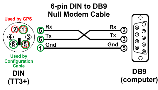
- Computer. You will create a configuration cable, as diagrammed here. The TT3+ must be configured with your call sign, packet parameters, etc. using the TT3+ configuration program*. This program will communicate with the TT3+ by a serial null-modem cable joining the TT3+ data cable pigtail (see above) to the computer's COM port. The TT3+ RX line listens for data from the GPS and also the computer via pin 5 (RX) on the pigtail's DIN. So the configuration cable's DIN pin 5 will also carry data from the COM port's DB9 pin 2 (TX). Conversely, the TT3+ TX line on the circuit board is connected to the pigtail's DIN pin 6, and also the configuration cable's DIN pin 6, sending its data to the computer via the COM port's DB9 pin 3 (RX). CAUTION: This cable should have NO CONNECTION to the 5V power line—the DIN plug's pin 2—that's ONLY used by the GPS, and would likely damage the COM port!
*See the TinyTrak3Plus zip file available from the Byonics.com web site, used to configure the TT3+ with your call sign, packet timing parameters, and so forth.
Newer computers typically have only USB ports (no serial port) and will require a convertor, such as this adapter cable or this one-piece adapter from amazon.com to deliver serial data, usually through a DB9 connection. Although this cable, adapter, and connectors can get rather clumsy, the good news is that you rarely need it after your initial setup procedure.
Operating Tip: When starting the TT3+ configuration program, it often requires some trial and error to get connected: connect the data cable, power up the TT3+ circuit, and start the program. Then in the program settings try COM1, COM2, etc. until the software recognizes the TT3+ circuit board. After making any changes, remember to "Write" (save) to the TT3+ any changes you make before closing the program or disconnecting the configuration cable. HINT: During configuration, if your modified battery pack is mounted to the radio, disconnect the microphone pigtail from the radio to avoid accidental TX.
- Antenna. A 2-meter antenna with a male BNC connector attaches to the Icom radio, such as this one from amazon.com. But any 2-meter antenna with a BNC connector that you can mount on your vehicle will work. NOTE: Remember to have an antenna (or dummy load) connected any time your system is powered.
- Power. For 12-volt power, you need a quick-connect system, such as a sturdy cigarette-lighter plug or a dual-plug connector (e.g., "power-pole" or similar). Inexpensive plugs typically fail to stay plugged in (or worse), so go ahead and spend an extra dollar on a good one!
Now that you've got your portable APRS tracker assembled and working,
←
go back to Page 1 and consider some of the operating tips provided there! Happy tracking!
|